I Made This Gameboy Pocket
Introduction
My Game Boy modding journey started in 2017, but I didn't get serious until 2021. I've learned a lot since then.
Like most people, I started by buying a Game Boy Color, reshelling it, and dropping in an IPS display kit. I also added an amp and a regulator I probably didn't need. My first real soldering project was building the GBPP, which introduced me to SMD work. Making several of those helped me develop my own techniques and figure out what actually works.
From there I tackled the DMGC, a much bigger challenge. With help from the community and Bucket Mouse, I got through it, and the experience taught me how to read schematics, understand PCB design, and troubleshoot properly. Since then I've worked through a variety of regulator designs, custom builds, and small PCB modifications. I'm still very much learning as I go, and I'll likely revisit this board as my skills grow.
IMT-MGB-01 Board
I'd been thinking about designing a Game Boy Pocket board for a couple of years. I wanted it to be one of my first projects that involved working from schematics and doing serious routing. Fortunately, there's a wealth of open resources available. Big thanks to Gekkio, Natalie The Nerd, Skimzor, and Bucket Mouse for their contributions.
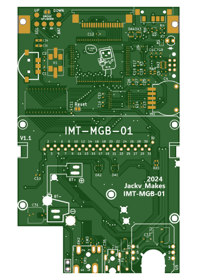
The board is called the IMT-MGB. IMT stands for "I Made This," a nod to a running joke in the community. MGB is Nintendo's internal model designation for the Game Boy Pocket.
Technically I did make it, but the heavy lifting had already been done by Gekkio. I pulled together a few resources and handled the routing. It's a good reminder of just how much knowledge is freely available out there, and I'm honestly surprised more people aren't getting involved and building things.
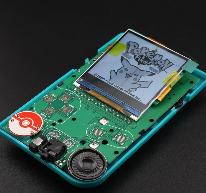
The IMT-MGB is a straightforward board designed to be as approachable as possible for someone with moderate SMD soldering experience. It cannibalizes components from a donor Game Boy Pocket along with a handful of additional parts. The OEM display circuitry is omitted intentionally since this board is meant to give new life to a Pocket with a dead display rather than start from scratch.
Features I built in include a set of optional tactile button pads, a toggle switch replacing the contrast wheel for brightness or palette switching (with bridgeable pads if your display kit only supports one function), and dedicated pads for A, B, and Select to simplify display kit wiring.
Functionally it behaves like a stock Game Boy Pocket. It's not meant to be an MGBC-level build. This was primarily an exercise in improving my KiCad skills, though I also designed it with others in mind. The MGBC boards can be intimidating, and working with fine-pitched ICs like the CPU and RAM isn't for everyone yet. This can serve as a solid intermediate step, though it's not a beginner project by any stretch.
Board files and ordering info: PCBWay Shared Project: https://www.pcbway.com/project/shareproject/IMT_MGB_Game_Boy_Pocket_17ee2181.html
GitHub:
https://github.com/Jackv-makes/IMT-MGB/
Ko-Fi shop (blank PCB boards):
https://ko-fi.com/jackvmakes/shop
Conclusion
After a few prototypes and rounds of revisions, I'm satisfied with where the board stands. I'm excited to see what others do with it, and I hope it encourages more people in the community to learn, experiment, and contribute.